4) Making a Motor Spin Quickly and Slowly
The Singer featherweight is a fantastic little machine, but for carting around on the back of a bike, it is just a little bit heavy. One area that could benefit from some nip ’n’ tuck is the rather beefy motor, weighing in at around 750 gramms on my machine. If I can replace this with a DC motor, also won’t need the inverter anymore. The original foot-pedal won’t work with a DC motor, so I will need a new one. This is not a big deal because the foot-pedal is a bit too well constructed for my purposes anyway. Between the motor, foot-pedal and inverter, I expect the machine to lose about a kilo, which when cycling uphill could make all the difference.
There are 3 parts to this conversion:
- the electronics to control the motor’s speed
- the design of the foot-pedal
- mounting the new motor and making it drive the machine
which I will talk about separately. But, take warning, although I may try to give the impression that everything was planned and thought out in a careful and compartmentalised manner, really it was a series of failed and retuned attempts.
Now its time to think about how to control a DC motor on my sewing machine. I need to have some kind of electronic circuit that is able to vary the speed of the motor nice and smoothly. Ideally that circuit will be matched perfectly to a foot-pedal in order to achieve the smooth control. I know hardly anything about electronics but I haven’t been electrocuted (yet).
Unfortunately, most of the motor control circuits that float around on google limit the current or voltage to get the motor to turn slowly. This is not ideal for a sewing machine as it means that when the motor is running slowly, it’s power is reduced, just at the point where you don’t want it to be - this might cause the machine to stall. Some circuits claim to beat this problem, but they were way too complicated for me to be able to solder together. I did consider employing a stepper motor, which doesn’t suffer from this problem. Some folks have managed to put stepper motors on sewing machines to make DIY embroidery robots: pretty cool. The downside of a stepper is that you need a driver circuit and they are heavier and more expensive - you win some and you lose some.
So keeping my DC motor I cobbled together a small pulse-width-modulation circuit that actually worked the first time. This works by turning the electricity to the motor on and off very quickly at a varying speed to alter the motor’s speed. My circuit used a potentiometer, essentially a knob that you turn to control the motor. Now the problem is converting the curved-arc motion of your foot pressing a pedal into the rotary motion needed to turn the potentiometer.
Cue sequence of 3D-printing many foot pedal designs from thingiverse…
Most of these designs used a curved gear to interface with a gear on the potentiometer. I found that in practice this interfacing was tricky to make reliable and wasn’t happy with any of the designs I saw as they seemed either too complicated to be reliable or not strong enough. I thought about buying a linear potentiometer, but that remained just a thought.
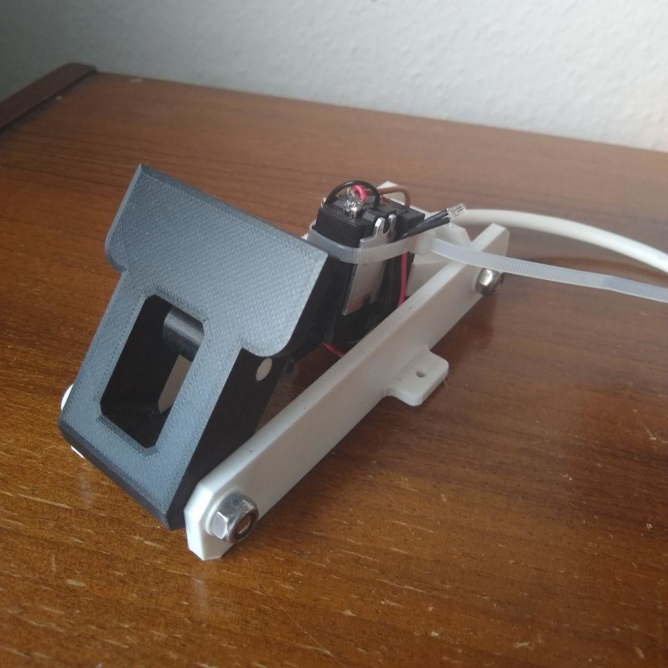
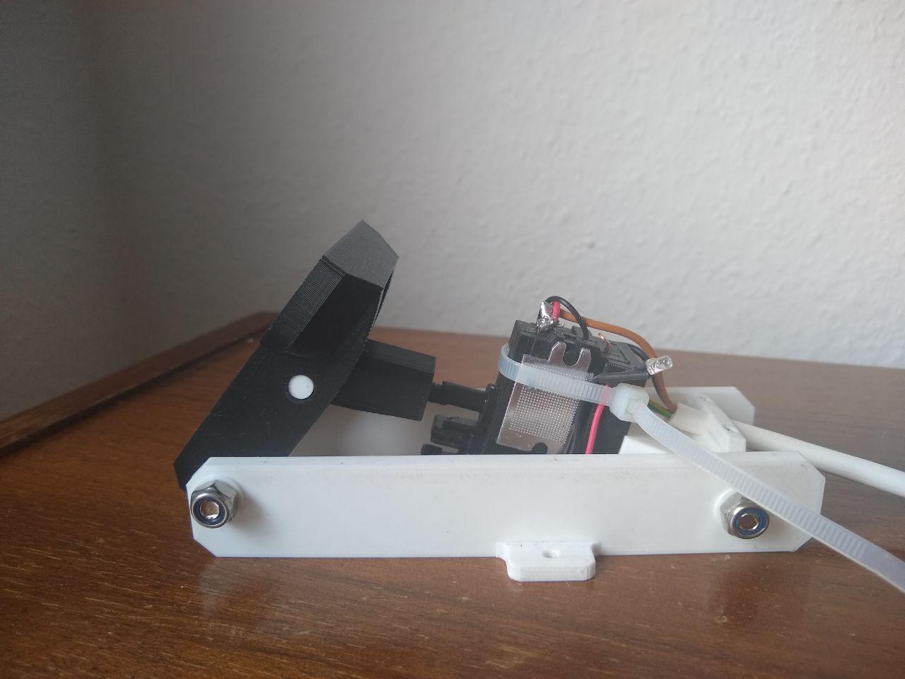
Then I stumbled across several designs for foot-pedals to be used in racing simulator games that seemed sturdy and simple to build . Instead of a pedal that where the pedal pivots around a hinge, a lever presses on a surface that is free to move around. Instead of the pedal moving in an arc, it moved in a straight line. I still had to find a way of turning the potentiometer.
That was until I realised that in a cordless drill, the required circuitry to make a motor go fast and slow is already there, and even better, it is controlled by a trigger that moves in a linear motion. The drill trigger is already neatly mounted in a little box so I really don’t have to do all that much - always the best solution. It is then not so hard to cannibalise a cordless drill and fit the control circuit into the 3D-printed foot-pedal. Essentially my sewing machine becomes just a glorified cordless drill.
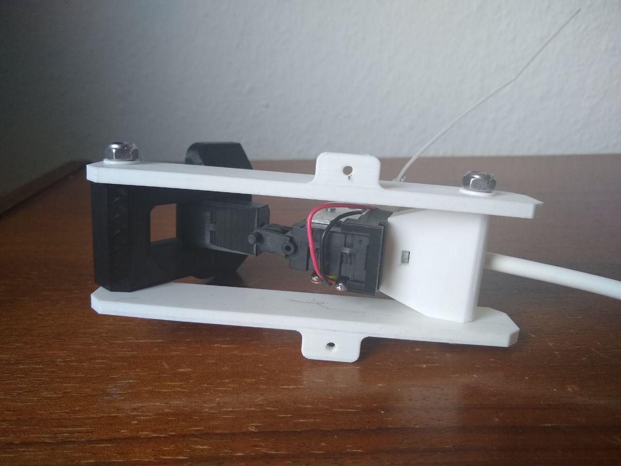
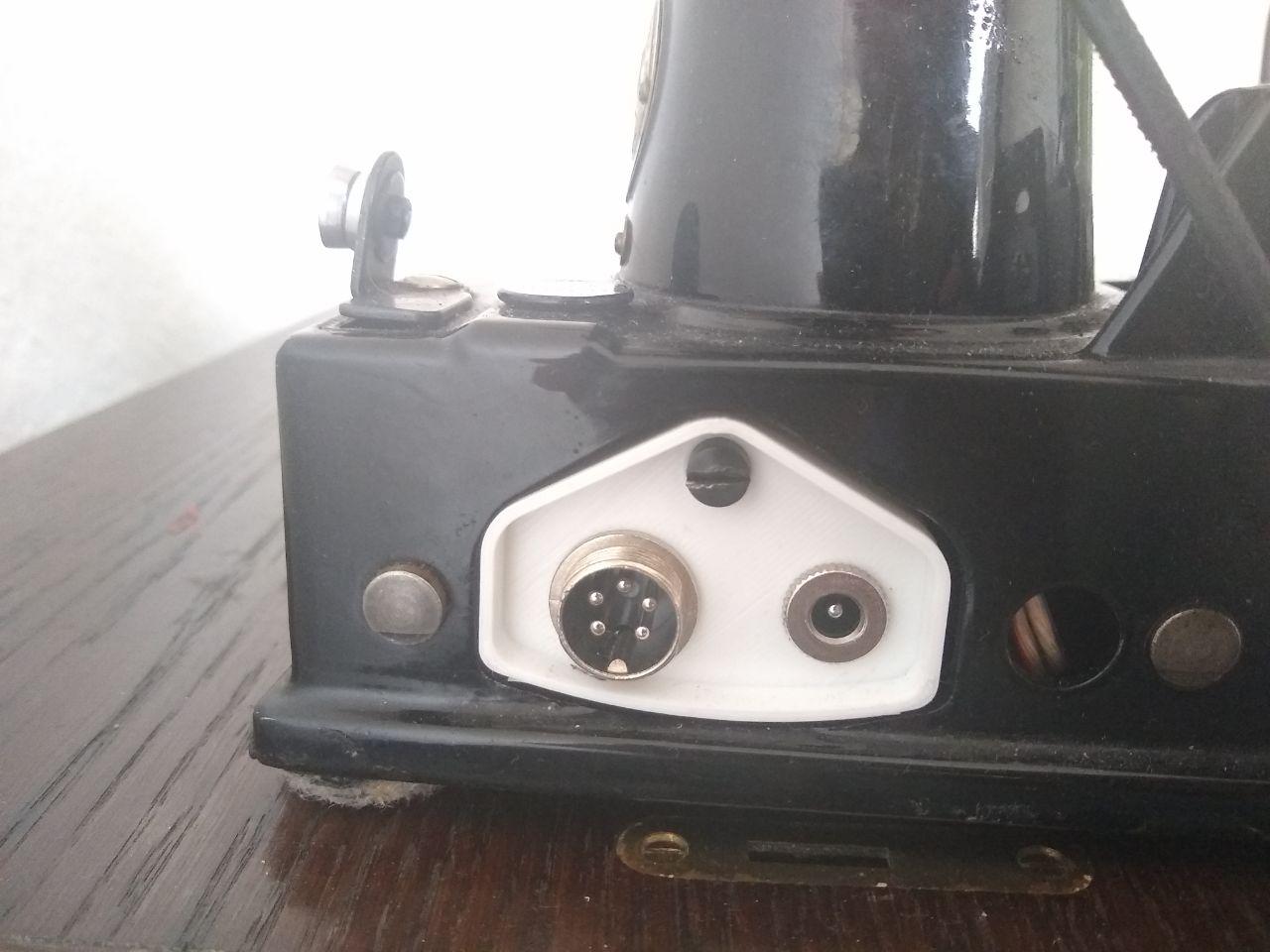
A piece of 4-stranded wire (two for the battery and two for the motor) runs from the pedal to the machine, where it connects to a DIN socket mounted onto the machine. The battery then connects to a separate barrel-jack next to the pedal socket. I managed to 3D print an near perfect copy of the original plug that can house the two connectors which I am very pleased with.
Now its time to think about how to fasten the motor to the machine and get it all turning.